
Integrating Nokia 7750-SR with Powerlynx doesn’t have to be a multi-day project. This guide walks you through the four Powerlynx-side configuration steps required to get your Nokia 7750-SR Wireless LAN Gateway (WLAN-GW) up and running as a managed hotspot – from NAS Type to the first verified session.
The Nokia 7750-SR is a Wireless LAN Gateway (WLAN-GW). Paired with Powerlynx, it handles splash page redirection, RADIUS authentication, and CoA/PoD session control for your users.
For Nokia 7750-SR WLAN-GW hardware configuration, contact your Nokia representative. This guide covers the Powerlynx platform side only.
How to Configure Nokia 7750-SR with Powerlynx: Step-by-Step Integration Guide
About Nokia 7750-SR WLAN-GW
The Nokia 7750-SR WLAN-GW handles RADIUS authentication, portal redirection, and session management for connected users.
The WLAN-GW operates in two user states: Migrant (unauthenticated, redirected to the splash portal) and full ESM (authenticated, plan applied). Powerlynx drives the transition between these states via RADIUS CoA after a user completes portal sign-in and selects a plan. The Nokia 7750-SR uses Site-to-Site IPSec for secure RADIUS connectivity to Powerlynx.
Requirements
- A Nokia 7750-SR with WLAN-GW function configured and operational.
- Access to the Powerlynx dashboard (Config, Portal, Networking, and Locations sections).
- The NAS-Identifier value that your WLAN-GW sends in Access-Request and Accounting messages.
- The RADIUS secret configured on your WLAN-GW for Authentication and Accounting.
- The Source IP address of the WLAN-GW ISA RADIUS policy (used as NAS-IP).
- The Nokia 7750 WLAN-GW CPM address (used as POD-IP / PoD source).
Configuration Overview
The Powerlynx integration for Nokia 7750-SR involves four configuration areas, completed in this order: NAS Type → Splash Page → IPSec VPN Tunnel → Location and Hotspot. Each step builds on the previous one – the NAS Type created in step 1 is referenced in the Hotspot created in step 4.
Detailed Steps
Step 1. Configure a NAS Type
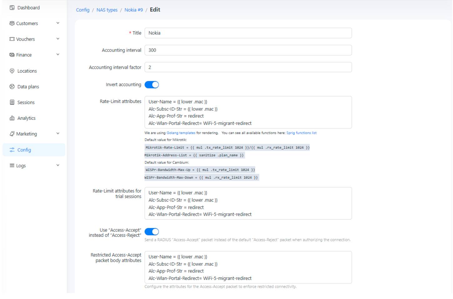
Navigate to Config → System → NAS Types in Powerlynx and create a new NAS Type profile. This profile defines how Powerlynx communicates with your WLAN-GW: the RADIUS VSAs sent in Access-Accept, the CoA attributes used to move users from Migrant to authenticated state, and the PoD attributes for session termination.
Key settings:
- Accounting interval – set this to match the RADIUS accounting policy update interval configured on your WLAN-GW.
- Invert Accounting – enable this.
- Use “Access-Accept” instead of “Access-Reject” – enable this.
Access-Accept attributes:
- Set the Alc-Wlan-Portal-Redirect value to match the http-redirect policy on your WLAN-GW (this is the portal redirect URL delivered to unauthenticated users).
- Use the .mac shorthand for the MAC address of the user equipment. Apply the lower() template function to convert to lowercase MAC format.
CoA attributes:
- Include sufficient VSAs to move the Migrant user to full ESM user state after successful portal sign-in and plan selection.
- Set Alc-SLA-Prof-Str and Alc-Subsc-Prof-String to match the SLA profile and Subscriber profile strings defined on your WLAN-GW.
- For time-based plans, use the .time_left shorthand. This reflects the remaining time since plan purchase – for example, a 24-hour plan will send 86400 seconds on first CoA, and the remaining seconds on each reconnection within that window.
PoD attributes:
- Include User-Name in lowercase MAC format.
Step 2. Create a Splash Page
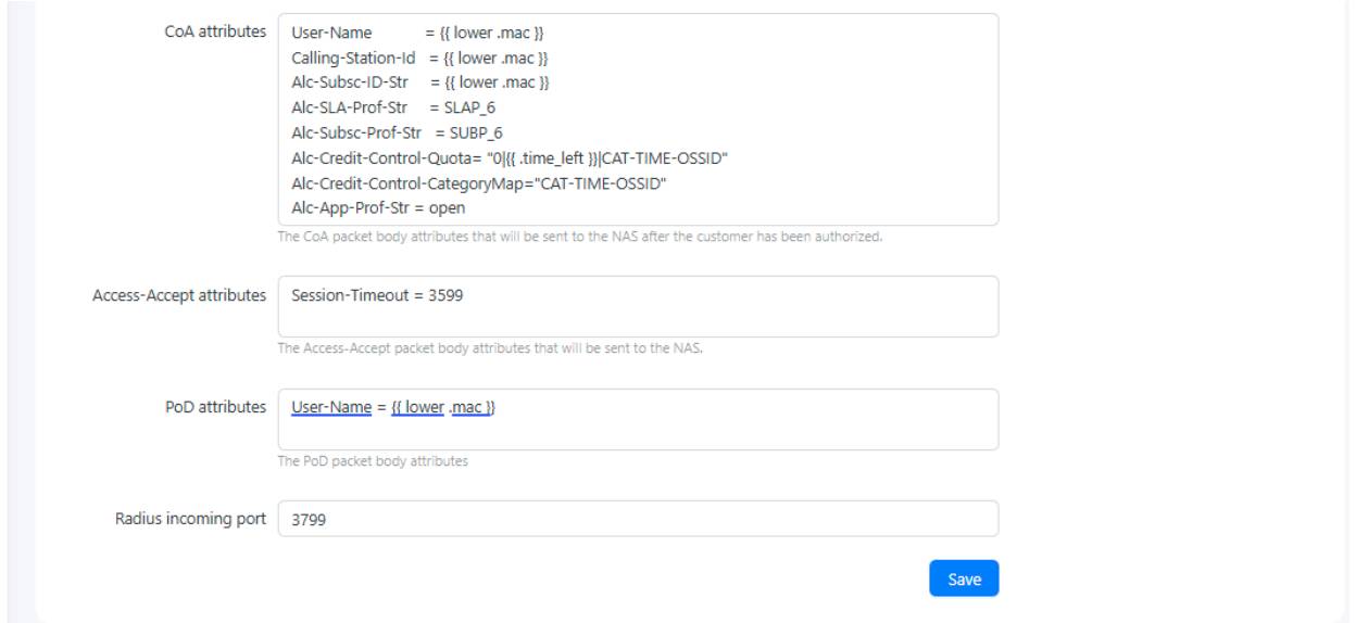
Navigate to Config → Portal → Splash Pages and create a new Splash Page. This defines the captive portal that unauthenticated users are redirected to when they connect to your WLAN-GW.
Configure the general parameters as required for your deployment. The critical field here is SSID.
!!! The SSID field must match exactly the NAS-Identifier value that your WLAN-GW sends in Access-Request and Accounting messages. This value is a key internal Powerlynx identifier used across multiple relationships in the platform. The value is derived from the Python policy on the WLAN-GW. !!!
Step 3. Set Up an IPSec VPN Tunnel
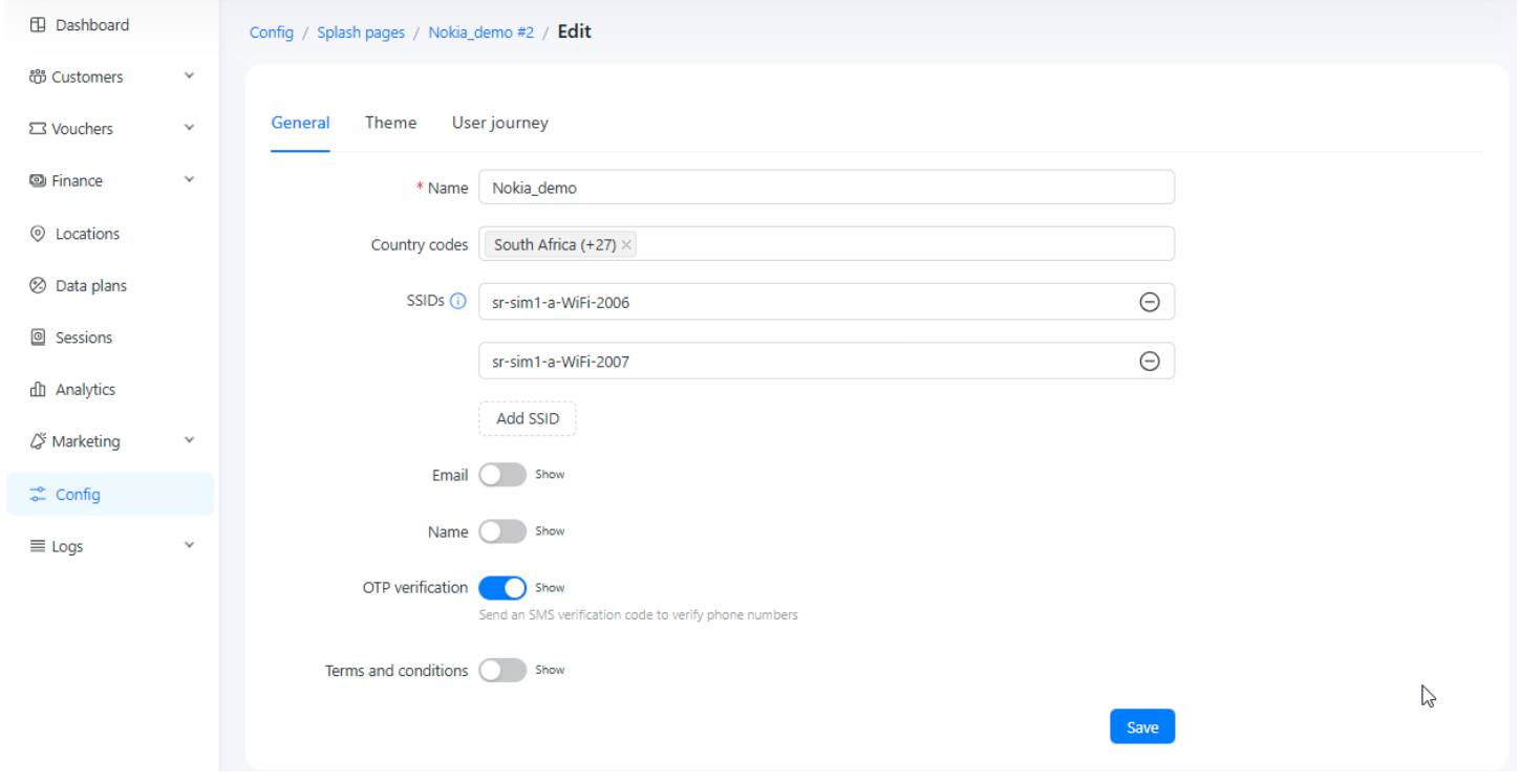
Navigate to Config → Networking → VPN Connections and create a new VPN connection. This establishes an IKE-based IPSec Site-to-Site tunnel that secures RADIUS connectivity between your WLAN-GW and the Powerlynx platform.
Configure the following fields:
- Connection mode: select Site-to-Site.
- Authentication mode: select Certificate.
- Private Subnets: enter the private subnet used for the RADIUS Client on your WLAN-GW. This is the subnet Powerlynx will route RADIUS traffic to through the tunnel.
Once saved, click Download in the Action column for this connection. You will receive a ZIP archive containing the certificates, keys, and configuration files required to be imported on the Nokia 7750-SR WLAN-GW side.
Step 4. Create a Location and Configure the Hotspot
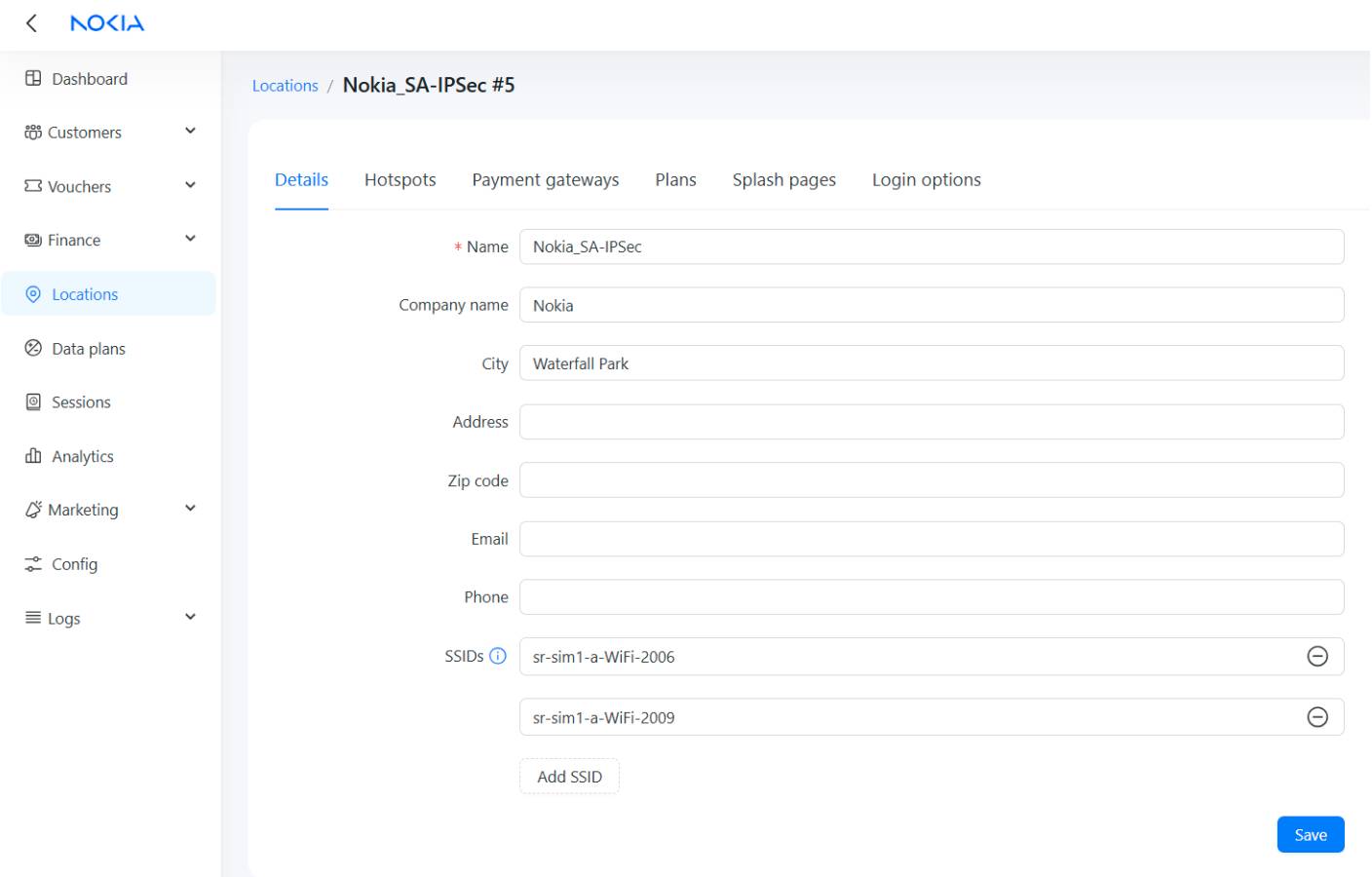
Navigate to Locations and create a new Location. A Powerlynx Location maps to a single Nokia 7750-SR WLAN-GW – one WLAN-GW can serve multiple SSIDs, and all of them can sit under this single Location.
Location details:
- Fill in the location details as required.
!!! The SSID field in the Location must match the NAS-Identifier value sent by your WLAN-GW in Access-Request and Accounting messages – the same value used in the Splash Page (Step 2). This is a key Powerlynx internal identifier. !!!
After saving the Location details, select the Hotspots tab and define a new Hotspot.
Hotspot configuration:
- NAS Type – select the NAS Type created in Step 1.
- RADIUS secret – must match the RADIUS secret defined in your WLAN-GW Authentication and Accounting configurations.
- NAS-IP – enter the Source IP address from your WLAN-GW ISA RADIUS policy.
- POD-IP – enter the Nokia 7750 WLAN-GW CPM address. This must correspond to the RADIUS Accounting source address on the WLAN-GW.
- VPN Connection – select the IPSec Site-to-Site connection created in Step 3.
Once configured, validate that connectivity is operational.
Nokia 7750-SR and Powerlynx: Integration Complete
With NAS Type, Splash Page, IPSec VPN, and Location configured in Powerlynx, your Nokia 7750-SR WLAN-GW is fully integrated: users are redirected to the splash portal, authenticated via RADIUS, moved to full ESM state via CoA after plan selection.
For full Nokia 7750-SR WLAN-GW hardware configuration, contact your Nokia representative. For Powerlynx platform documentation, visit docs.powerlynx.app.